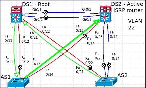
Part 3 will cover VLAN 22. Again, this is intentionally misconfigured to show how to use dia to document a spanning tree instance and to help find any problems.
Again, let's start with the base map that shows all the physical connections:
Just like on Part 1 and Part 2, let's start with a 'show spanning-tree vlan 22' command on DS1:
First thing we can see is that DS1 is the spanning tree root switch and that Gi0/1 and Gi0/2 are not involved in this instance. Let's document the links on the dia map.
On to DS2. Again starting with the 'show spanning-tree vlan 22' command:
The trunks are a little different on this switch. All six connections are involved with the spanning tree instance for VLAN 22. Fa0/13 is the root port and Fa0/14 is blocking to prevent a loop between DS2 and AS1. Let's document this on the map.
Note that the blue Gigabit links are showing that DS2 is forwarding traffic but that the VLAN is not allowed on the trunk link configuration on DS1. The circled-x's are used to show which end of the connection does not have the VLAN allowed on the port. The red link is used to show that one end of the connection is in a blocking state. The arrow on the Fa0/13 from DS2 to AS1 is used to show which port is the root port back to the root switch (DS1 on this VLAN).
Let's head over to AS1:
No surprises here. Fa0/11 is the root port back to DS1, Fa0/12 is blocking to prevent a loop and both ports to DS2 are forwarding.
Here we see that only two of the trunk links are forwarding for VLAN 22: Fa0/21 and Fa0/22 over to DS1.
So now we have a complete picture of the Layer 2 spanning tree topology. Next, let's check out how HSRP is configured.
And DS2 confirms that DS2 is indeed the HSRP active router for VLAN 22.
So, what does this mean?
Well, spanning tree is used only for loop prevention. Spanning tree doesn't care that the default router is not the spanning tree loop. So, in this case, any traffic originating from AS2 will go through DS1, then to AS1, then to DS2 exit the VLAN.
We can update the map to show that spanning has converged correctly, but that DS2 is the default gateway out of the VLAN, like so:
With this final map, we can see that spanning tree is using DS1 as the root bridge but that DS2 is the default gateway. I've turned the arrows around to point to DS2 as the default gateway and increased the size of the link between DS2 and AS1 to show that we have a really inefficient configuration for this VLAN. From AS2's perspective, all traffic goes to DS1 since that is the root switch, but then DS1 will have to send the frame to DS2 to exit the VLAN (such as traffic heading to the Internet). On this VLAN, AS1 then becomes a transit switch instead a pure access layer switch.
So, what should be done to fix this unfortunate configuration?
First, DS2 should either be set as the root switch or changed to be the HSRP standby router for the VLAN. Second, VLAN 22 should be added to all the trunk links so that VLAN 22 traffic can be sent directly to the HSRP active router and to make use of the Gigabit connections between DS1 and DS2.
Part 4 will tackle VLAN 33.
Thank you for reading!


No comments:
Post a Comment