Thursday, August 1, 2013

Troubleshooting Trunk Links and Spanning Tree using Dia - Part 3 of 5

Welcome back!

Part 3 will cover VLAN 22.  Again, this is intentionally misconfigured to show how to use dia to document a spanning tree instance and to help find any problems.

Again, let's start with the base map that shows all the physical connections:


Just like on Part 1 and Part 2, let's start with a 'show spanning-tree vlan 22' command on DS1:


First thing we can see is that DS1 is the spanning tree root switch and that Gi0/1 and Gi0/2 are not involved in this instance.  Let's document the links on the dia map.


On to DS2.  Again starting with the 'show spanning-tree vlan 22' command:


The trunks are a little different on this switch.  All six connections are involved with the spanning tree instance for VLAN 22.  Fa0/13 is the root port and Fa0/14 is blocking to prevent a loop between DS2 and AS1.  Let's document this on the map.


Note that the blue Gigabit links are showing that DS2 is forwarding traffic but that the VLAN is not allowed on the trunk link configuration on DS1.  The circled-x's are used to show which end of the connection does not have the VLAN allowed on the port.  The red link is used to show that one end of the connection is in a blocking state.  The arrow on the Fa0/13 from DS2 to AS1 is used to show which port is the root port back to the root switch (DS1 on this VLAN).

Let's head over to AS1:


No surprises here.  Fa0/11 is the root port back to DS1, Fa0/12 is blocking to prevent a loop and both ports to DS2 are forwarding.


Last, let's head over to AS2:


Here we see that only two of the trunk links are forwarding for VLAN 22:  Fa0/21 and Fa0/22 over to DS1.


So now we have a complete picture of the Layer 2 spanning tree topology.  Next, let's check out how HSRP is configured.


On DS1, we can see that DS1 is running as the standby HSRP router for VLAN 22.  Let's check DS2 to verify.


And DS2 confirms that DS2 is indeed the HSRP active router for VLAN 22.

So, what does this mean?

Well, spanning tree is used only for loop prevention.  Spanning tree doesn't care that the default router is not the spanning tree loop.  So, in this case, any traffic originating from AS2 will go through DS1, then to AS1, then to DS2 exit the VLAN.

We can update the map to show that spanning has converged correctly, but that DS2 is the default gateway out of the VLAN, like so:
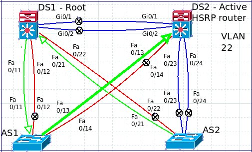

With this final map, we can see that spanning tree is using DS1 as the root bridge but that DS2 is the default gateway.  I've turned the arrows around to point to DS2 as the default gateway and increased the size of the link between DS2 and AS1 to show that we have a really inefficient configuration for this VLAN.  From AS2's perspective, all traffic goes to DS1 since that is the root switch, but then DS1 will have to send the frame to DS2 to exit the VLAN (such as traffic heading to the Internet).  On this VLAN, AS1 then becomes a transit switch instead a pure access layer switch.

So, what should be done to fix this unfortunate configuration?

First, DS2 should either be set as the root switch or changed to be the HSRP standby router for the VLAN.  Second, VLAN 22 should be added to all the trunk links so that VLAN 22 traffic can be sent directly to the HSRP active router and to make use of the Gigabit connections between DS1 and DS2.

Part 4 will tackle VLAN 33.

Thank you for reading!

Wednesday, July 31, 2013

Troubleshooting Trunk Links and Spanning Tree using Dia - Part 2 of 5

Continuing the series on using Dia to troubleshoot trunk links and spanning tree instances, let's move on to VLAN 11.

We start with the original dia map (no colored links) to show the physical topology:


Let's start with the 'show spanning-tree vlan 11' command:

DS1:

We can see that under the Root ID section that this switch is the root and that all the ports are in the Designated - Forwarding state.

However, notice that neither of the Gigabit ports are listed.  Only the FastEthernet ports are forwarding.  So, here is the first time we are seeing an issue with the current configuration.

Documented on dia as such:

Over to DS2 now.  Again, we start with the 'show spanning-tree vlan 11' command:

DS2:

On this switch, we can see that Fa0/13 is being used as the connection back to the root switch (DS1 in this case, now labeled on the dia map).  Fa0/14 is blocking to prevent a loop between DS2 and AS1.  Both connections from DS2 to AS2 are forwarding traffic.  Since VLAN 11 is not on the Gigabit connection between DS1 and DS2, I have left the links black to show that they are physically connected but not involved in the spanning tree instance.


Next, AS1 and the 'show spanning-tree vlan 11' command:

AS1:

AS1 is behaving as expected.  Interface Fa0/11 back to DS1 is the root port, Fa0/12 is blocking and Fa0/13 and Fa0/14 are designated ports back to DS2.


Last, let's head over to AS2 and run the 'show spanning-tree vlan 11' command:


On AS2, we see that only Fa0/23 and Fa0/24 are involved in the spanning tree instance for VLAN11.   Here is the final map:


So, with the help of our dia map, we can see that traffic on VLAN 11 originating from AS2 has to go through two switches to get back to the root switch (AS2 to DS2 to AS1 to DS1).  This is also confirmed by the Cost listed under the Root ID section of the 'show spanning-tree vlan 11' command on AS2.  The cost of a FastEthernet link is 19 and there are 3 FastEthernet links back to the root, so 19 times 3 equals 57.

So, what is the cause of the problem?  I would start with checking out the trunk configurations on each switch, but especially the trunk configuration on AS2.  

Let's run the 'show interfaces trunk' command on each switch.

DS1

Here we can see that under the 'Vlans allowed on trunk' section that VLAN 11 is not allowed on Gi0/1 and Gi0/2 (which we documented on the map).

DS2

Same configuration on DS2.  Under the 'Vlans allowed on trunk' section, VLAN 11 is not listed.

AS1

On AS1, VLAN 11 is allowed on all ports and that is also documented on the map (two designated ports, two blocking ports).

AS2

And here we can see that VLAN 11 is allowed on Fa0/23 and Fa0/24 (root port and blocking port), but that VLAN 11 is pruned from Fa0/21 and Fa0/22 (which are the direct links back to DS1).

Now, what about HSRP (aka the default gateway) out of VLAN 11?

Let's run the 'show standby vlan 11' command on DS1 and DS2:

DS1

Right away, we can see that DS1 is the 'Active' router for VLAN 11.

So for any traffic originating from AS2 on VLAN 11 and would need to leave the VLAN, the frames would be forwarded from AS2 to DS2 to AS1 to DS1.  Not efficient at all!

So, what would be the best way to fix these problems?

VLAN 11 should be added to all the trunk links especially the Gigabit links between DS1 to DS2 and also the links between DS1 and AS2 so that AS2 as a direct link to the HSRP router (aka the default gateway).

VLAN 11 should match VLAN1 in this instance.

I hope you can see how using dia and a few IOS commands can show you how spanning tree is running and how looking at the trunk configuration is fundamental at fixing spanning tree configurations.

VLAN22 is up next.

Thank you for reading!

Tuesday, July 30, 2013

Troubleshooting Trunk Links and Spanning Tree using Dia - Part 1 of 5

A few weeks back, we replaced a Cisco chassis with a newer model.  As part of the verification process, I checked the spanning tree output and noticed some discrepancies.  For example, some of the VLANs were using the first distribution layer switch as the spanning tree root while other VLANs were using the second distribution layer switch as the root.

In order to get a visual of the current spanning tree instances, I chose to use the open source program Dia (http://dia-installer.de/).  Dia has a number of Cisco icons to be used.  One problem I noticed is that if I use the straight lines to connected icons together it is impossible to make redundant links.  However, using the arc line type, we can offset the lines to show redundant links.


So, using my home lab equipment, I've set up an example to show how Dia can be used to map out spanning tree instances.

I have two 3550s as Distribution Layer switches (DS1 and DS2) while two 2950s are set as Access Layer switches (AS1 and AS2).  The VLANs in place are:  1, 11, 22, 33 and 44.

The black lines are the physical layer (cable) connections:


 VLAN 1 will be the Management VLAN and the native VLAN on the trunks.  HSRP is also configured for each of the VLANs.

VLAN number = x
  Default Gateway:  10.1.x.1 255.255.255.0
  DS1:  10.1.x.11
  DS2:  10.1.x.12
  AS1:  10.1.x.13
  AS2:  10.1.x.14

Let's start with a 'show spanning tree summary' command on each switch:
DS1:

Note that DS1 is the Root bridge for VLANs 1, 11, 22 and 33.

DS2:

Again, note that DS is the Root bridge for VLAN 44.

AS1:

AS1 is not a Root bridge for any VLANs, which is what we want and expect.

AS2:

So, here is our first sign of a problem.  AS2 is showing itself as the Root bridge for VLAN 44.  However, DS2 also thinks it is the Root bridge for VLAN 44.  So, we obviously have a problem with our trunk links and/or spanning tree.

Next, let's take a look at the spanning tree instances:
DS1 - VLAN 1

We can see that DS1 believes it is the root for VLAN 1 and that all the trunks are Designated ports and are in FWD (forwarding) status.

So, in Dia, we copy the original layout and rename it (for example, VLAN-1.dia) and we then change the links from DS1 to green to show that they are Designated ports.  To change the color of the link, double-click the link and change the drop box named 'Line Color' from black to green.


Now that VLAN 1 on DS1 is documented, let's move over to the other distribution switch.
DS2 - VLAN 1

Here we can see that the FastEthernet ports are Designated ports, Gi 0/1 is the Root port (the port that is being utilized to access the Root bridge) and that Gi 0/2 is an Alternate port and is in the Blocking state.  When we look at the topology in Dia, we can see that if Gi 0/2 was in a Forwarding state that a loop would occur.  To document the blocking port, I suggest changing the link color to red and using the circled X located in the SDL icon section:


It is large when it is brought over to the map, so it will be necessary to resize the icon.

I also add an arrow for the Root port to show the direction toward the Root bridge.  To add an arrow, double-click the line and choose an arrow style from the drop down box labeled either 'Start Arrow' or 'End Arrow'.

Here is the diagram once DS2's perspective of the VLAN is added:


Moving on to AS1:
AS1 - VLAN 1

Here we can see that AS1 is doing most of the blocking for the triangle between DS1, DS2 and AS1.  Fa0/11 is Root port back to DS1 (the root bridge) while the rest of the ports are blocking to prevent a loop between DS1, DS2 and AS1 and the loop between the dual uplinks between DS2 and AS1.  Here is the updated diagram:


And now to finish it off, let's go through AS2:
AS2 - VLAN 1

Same type of blocking as before on AS1:  we have a Root port back to DS1 while the rest of the trunks are in Blocking.

And so the finished map looks like this:

Everything here looks great.  One link from each switch going directly to the Root bridge.

Since HSRP is being used for gateway redundancy, let's check that out using the 'show standby vlan 1' command on DS1 and DS2.


DS1 is the Active gateway.  This is verified by the 'State is Active' and 'Active router is local' lines.

DS2 should appear as the standby router:


And it is.  This is verified by the the 'State is Standby' and 'Active router is 10.1.1.11, priority 250' lines.

It is important to verify what router (or Layer 3 switch in this lab) is the default gateway as we will see later on.

The next four VLANs (11, 22, 33 and 44) has been intentionally misconfigured to show how to use Dia to diagram the spanning tree instances to find problems with the trunk configurations.

Part 2 will be for VLAN 11.

Thank you for reading!


Thursday, July 18, 2013

Three Years of "Don't Break the Chain"

On July 18th 2010, I read about the “Don’t Break the Chain” habit on lifehacker.com.  I’m proud to say that today marks three years of daily study on Cisco and networking technology.  Because of this method, I’ve passed three Cisco exams (CCENT, CCNA and CCNP SWITCH) and I am working towards the next two exams to earn the CCNP and then on to the CCIE.  If you have a goal (or multiple goals), I highly recommend this method.  
If you want to read about the story behind the method, here is a link:  http://lifehacker.com/281626/jerry-seinfelds-productivity-secret
Start your own chain at:http://dontbreakthechain.com

Saturday, April 13, 2013

Broadcasts Only?

This last week I was called on an issue involving a specialized device that had lost communication with the network.  I am going to write this up in the same order in which we found more information and then ultimately came to the solution.

But first, a little background on the device.  The device is on a secured network behind a firewall and uses a statically assigned IP address (no DHCP).  However, the device does use broadcast packets and unicast packets to communicate with other devices on this network (sorry that I can't give more details about the devices themselves, but that's how it has to be).

So, let's start with our network topology using dia (http://dia-installer.de/).  This is just the physical topology using my home lab equipment, but this will be enough to show the issue and the solution.  There are three switches which are connected in succession.


On this network we have three VLANs:  one for the switch management, one for the typical end users and one for these devices.  We will use VLAN 1 for the switch management, VLAN 52 for the end users and VLAN 57 for the devices.  The device having the issue will be located on VLAN 57.

So, one of my first steps is to always check the interface (#show int fa 0/8),


 check the port security (#show run int fa 0/8),


 and the port's configuration (#show run int fa 0/8).


The port interface is up and no port security violations are occurring.  Typically at this point, I clear the interface counters to see if packets are flowing in both directions (#clear counters fa 0/8).  Then, another look at the interface statistics (#show int fa 0/8).


Notice that the only type of packets coming from the device to the switch are broadcast packets since the counters are identical (13 packets inputs).  There is also some traffic leaving the switch going to the device (9 packets output).

So at this point, I'm thinking that the device is misconfigured since these devices are using static IP addresses, maybe the device has the wrong subnet mask or default gateway configured.  Unfortunately, I forgot the phrase about assumptions and I made an 'ass out of me'.   Since I spend most of my work time at the access level (Layer 1 and Layer 2 with a sprinkling of Layer 3), I was really focused on the local connection, not the upstream connection.

After the end user put another known good device on the same port, it still had the same problem (could not communicate to other devices on the same subnet).  At that point, I started looking at the trunk links.

Ran a #show int trunk to look at the allowed VLANs and VLAN 57 was allowed:


Next, a look at the spanning-tree instance for VLAN 57:


No problems there.  Fa0/2 is the trunk link up to the next switch and is the root port (the path to the root switch which is BackboneSwitch).

Time to move up to the next switch to see what is going on there.

First, the same #show int trunk command to make sure the correct VLANs are allowed:


Same deal here.  VLAN 57 is allowed in both directions (down to Switch2 and up to BackboneSwitch).

Next, a look at the spanning-tree instance for VLAN 57:


Now, are you seeing what I'm seeing?


Switch1 should not be the spanning-tree root for any VLAN; BackboneSwitch should be the root.  However, the VLAN is allowed on the trunk up to BackboneSwitch.  So, what is the problem?

Time to go to BackboneSwitch and check the configuration there.

So we run the #show int trunk command one more time and find:


VLAN 57 is not allowed on the trunk link.  Somehow (and after checking the logs, we still don't know how or why) VLAN 57 was removed from the trunk going to the two downstream switches effectively cutting the VLAN from the rest of the network.

For a VLAN to be active through the whole topology, the VLAN number must be allowed on both sides of the trunk link.

So a quick change to the interface (config-if)#switchport trunk allowed vlan 1,52,57

The VLAN was reconnected to the rest of the network, spanning-tree converged and the device was back on the network communicating with the other devices on the subnet.

This same type of packet flow (all broadcasts but unable to grab a DHCP lease or communicate with other devices) will also happen if the port is added to a VLAN that either doesn't exist on the switch or if that VLAN is not allowed out the trunk.

So, the moral of this story:

Connectivity issues are not always at the device end.  It may be an issue two or three switches upstream that is the cause of the problem.

Unfortunately for me (since I spend most of my troubleshooting time at the device end), it took me way too long to start checking the entire path.  I was convinced that the problem was with the device, not the switch configuration.  My customer was frustrated with me and I am still kicking myself for wasting my customer's time and for not figuring out the issue quicker.

Monday, March 25, 2013

Free PDF from CCIEx2 Kevin Wallace. Highly recommended!

CCIEx2 (Routing/Switching and Voice) Kevin Wallace is offering his PDF ebook, Your Route to Cisco Career Success, for free!

http://www.1examamonth.com/products/

If you are working towards any certifications (even certifications outside of Cisco), there are many great ideas in this book.

I enjoy watching his informative YouTube videos as well.

http://www.youtube.com/feed/UCa5DwgTjlWMObHDIm6-zv1A/u

Great read, highly recommended!

Saturday, March 16, 2013

Home Lab Setup

I recently purchased a network rack to hold my Cisco equipment in my home lab.

The rack is an Onstage RS7030 Rack Stand purchased through Amazon.com:

http://www.amazon.com/dp/B000CD1R84/ref=pe_175190_21431760_M3T1_ST1_dp_1


So the Cisco gear from top to bottom is as follows:

3)  Cisco 1721 routers
2)  Cisco 2621 routers
3)  Cisco 2950 switches (Layer 2 only)
2)  Cisco 3550 switches (Layer 3 capable)

The wicker basket holds all of the cables I'm not using at the time.

The rack seems very solid.  One complaint is that it is that the vertical bars are intended to be angled back which makes it difficult to use the tray I purchased to hold my Cisco 1721 routers (which are not rack-mountable).  So, I undid two of the bolts, rotated the vertical bars so they are more vertical and replaced the bolts.  So instead of the bolts holding the support, the support is resting on top of the bolts.  Kind of clunky to have it that way, but I like it better this way.


Also, the mounting bolts are not great.  They work just fine, but I purchased some Raxxess mounting screws.

http://www.amazon.com/dp/B0001FTVD6/ref=pe_175190_21431760_3p_M3T1_ST1_dp_1

Lastly, I purchased a 100 pack of cable marker ties to identify each cable.  It has been really nice when moving cables around knowing exactly which ends I'm dealing with.

http://www.amazon.com/dp/B003L13A7K/ref=pe_175190_21431760_3p_M3T1_ST1_dp_1

If you are putting together a home lab, the Onstage RS7030 rack is a great way to rack up your routers and switches.